Table of Contents
Motivation
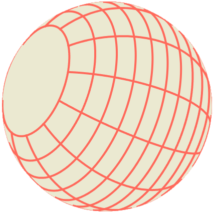
This was the first simulation I did for this website and it is more a simple mathematical exercise. We can look into the dynamics of bouncing off the edge, how to get the grid on the ball and how to rotate it every step.
Bouncing off
Bouncing off the Edge
If the ball touches the edge, its direction is rotated such that the angle between the wall and the direction-vector are the same before and after the impact.
We can describe the wall as a line with an offset vector and a direction vector:
If the center of the ball is closer to the wall than the ball’s radius the ball needs to bounce off the wall, let’s call the direction the ball is traveling in at this moment .
We call the smaller angle between and .
Now we only need to rotate about an angle of .
Notice that in this example the angle is negative and if we take the smaller angle between and it would be positive. Generally, an angle is positive if it goes counterclockwise and positive if it goes clockwise. The rotation matrix for this rotation is
The calculation we have done is applicable to any not only those that are vertical. But let’s now consider a wall that is vertical to understand how we could check whether the center of the ball is closer to the wall than the ball’s radius. With a vertical wall, that is easy just look at the -coordinate of the ball’s position and the -coordinate of , if their difference is smaller than the radius the ball and the wall overlap. But this does not seem to work generally.
We can see that by generally just looking at the coordinates we are not really measuring the shortest path to the line and we also notice that the shortest line is always orthogonal to the line. Let’s look at a line that goes through the center of the coordinate system, and also draw in the center of the ball, :
We can see that we need to find the length, , of the thin line orthogonal to the wall and we can use trigonometric functions to do so if we have the angle between the two vectors:
However, we do not need to calculate if we remember the relationship between sine and cosine and cosine of an angle between vectors and the vectors themselves:
is the angle between the normal vector of the wall, , which is just the wall direction rotated by 90 degrees, with the rotation matrix we discussed before. In total that means
Also, a rotation does not change the length of a vector and rotating by 90 degrees is just swapping the coordinates and adding a minus to the new -coordinate:
So now we have
which looks a lot simpler than the calculations including the angle we had before.For a general wall that does not go through the center, we just need to move our coordinate system so that it does go through the center which we achieve by subtracting the lines offset vector by every position vector. Also, one line has two possible direction vectors that make up the same line since we could rotate the direction vector by 180 degrees and get the same line. We relied on the direction vector being the one that when rotated by 90 degrees points towards the center of the ball. We can ensure that is true by requiring the normal vectors of all walls to point inwards, into the field. If we forgot to consider this we would get negative values for our length, . The first problem we fix by adjusting our formula:
and the second we could fix just by taking the absolute value of . We have a bounce whenever is smaller than the radius of the ball.
Bouncing off the mouse
The mouse effectively works as a wall that is always orthogonal to the vector between the mouse and ball position, so every time we check for a bounce, we just add a wall with the offset, , equal to the mouse position and the direction
Because the wall direction is orthogonal to the vector between mouse and ball position the shortest path should always just be the length of that vector. Since, as previously established, the shortest path is always orthogonal to the wall direction. Let us call the mouse position vector . Remember and since in this case, so:
as we expected. Also notice exactly which direction vector we took for the wall: . If we rotated with an angle of the normal vector of the wall would be pointing in the wrong direction, in fact, , which intuitively makes sense, the normal vector of the wall points towards the ball center.
Grid of the Ball
One way to do this is to keep track of the rotation of the ball and then calculate every point of the ball’s gird every frame. Depending on how many points we use to make the grid look like it is a smooth curve and connects to the edge of the circle this is not very performant compared to the second solution: keeping calculating all points at the beginning and then rotating them every step.
The latitude lines are the lines that go parallel around the ball, horizontally, if we think about the earth positioned such that the north is up. If the ball’s center is the center of our coordinate system we need to go up a certain height then at that height, we go right until we reach the surface of the circle. Then we rotate this vector around to get every point on this one latitude line, and change the height until we have every latitude line we want:
function makeLatitudeLines() {
  const latitudeLinesCount = 6
  const ballDiameter = 2 * ballRadius
  const result: Vector3[][] = []
  for (let i = 0; i < latitudeLinesCount; i++) {
    result[i] = []
    // latitudeLinesCount + 2 since we do not want lines at
    // the very bottom or top
    const distanceBetweenLatidudeLines
      = ballDiameter / (latitudeLinesCount + 2)

    // i + 1 since for i = 0 we would be at the very bottom
    // if we used i
    const height
      = (i + 1) * distanceBetweenLatidudeLines - ballDiameter

    // make point such that its at height and on the surface of the ball
    const currPoint
      = new Vector3(Math.sqrt(ballRadius ^ 2 - height ^ 2), height, 0)
    for (let angle = 0; angle < 360; angle++) {
      currPoint.rotateAround(Vector3.e2, Math.Pi / 180)
      result[i].push(currPoint.copy())
    }
  }
  return result
}
The longitude lines are a little more complicated since they are not parallel, we first go ballRadius units left to reach the surface of the ball then we rotate the resulting vector, currPoint, about the angle of the longitude line. This vector and the vector span the plane that the longitude line is in, in fact, the longitude line is the intersection of the circle surface and this plane. So we can now rotate currPoint in this plane, using the normal vector of the plane to do so. The normal vector of a plane can be constructed by taking the cross product of the two spanning vectors.
function makeLongitudeLines() {
  const longitudeLinesCount = 6
  const ballDiameter = 2 * ballRadius
  const result: Vector3[][] = []

  for (let i = 0; i < longitudeLinesCount; i++) {
    result[i] = []
    // go on the surface of the ball
    const currPoint
      = new Vector3(ballRadius, 0, 0)

    // rotate onto the longitude line plane
    const rotationDelta = (360 / longitudeLinesCount) * (Math.Pi / 180)
    currPoint.rotateAround(Vector3.e2, i * rotationDelta)

    // construct the normal vector of the plane we
    // need to rotate in
    const rotationAxis = currPoint.crossProduct(Vector3.e2)

    for (let angle = 0; angle < 360; angle++) {
      currPoint.rotateAround(rotationAxis, Math.Pi / 180)
      result[i].push(currPoint.copy())
    }
  }
  return result
}
In both of these functions we are using the rotateAround function, this function takes a rotation axis and an angle to rotate a vector in 3 dimensions. Let’s look into this function in more detail starting with the first case, rotating around the vector Vector3.e2 . If the first coordinate is left and right, the second is up and down and the third is forward and backward this rotation axis rotates in the left/right, forward/backward plane. Rotating in this plane basically gives us a 2- dimensional coordinate system that we can project our vector into by just removing its second coordinate, we can rotate the resulting vector like we are used to in 2 dimensions and add back its second coordinate to get the rotated vector. Luckily a general rotation is not much more complicated just that we project into any plane given by the rotation axis and then do the inverse projection after we are done rotating.
function rotateAround(
  vectorToRotate: Vector3,
  rotationAxis: Vector3,
  angle: number) {
  // rotation in 2 dimensions
  const rotation = new Vector2(1, 0)
  rotation = rotation.rotate(angle)

  // take the norms of the rotation axis vector
  // not doing this will mess up the length of the vectors
  // we construct in the next step, we rely on the ratation axis
  // having no influence in their length as expected of a rotation

  const normRotationAxis = rotationAxis / Math.abs(rotationAxis)

  // seperate the vector thats going to be rotated into
  // parts parallel and orthogonal to the rotation axis
  // the ortogonal part is in the rotation plane
  // the first * is a dot product and the second
  // a scalar multiplication
  const parallelToAxis
    = (normVectorToRotate * normRotationAxis) * normRotationAxis
  const orthorgonalToAxis = normVectorToRotate.subtract(parallelToAxis)

  // now we rotate orthorgonalToAxis around the rotationAxis

  // n is ortogonal to both
  // orthorgonalToAxis and normRotationAxis, so it and
  // orthorgonalToAxis span the rotation plane
  // notice that |n| = |orthorgonalToAxis|
  const n = Vector3.crossProduct(orthorgonalToAxis, normRotationAxis)

  // we now rotate in the plane described by orthorgonalToAxis and n
  // so we need to multiply those vectors by the rotation we did
  // at the top to get the rotation in the canonical 3D basis

  // notice that norming both basis vectors here and then multiplying
  // by the length of orthorgonalToAxis is the same thing as we do here:
  // |oTA| (r.x oTA/|oTA| + r.y n/|n|)
  //    = |oTA| (r.x oTA/|oTA| + r.y n/|oTA|)
  //    = r.x oTA + r.y n
  const rotatedInPlane = rotation.x * orthorgonalToAxis + rotation.y * n

  // lastly we add back the parallel part
  return parallelToAxis + rotatedInPlane
}
The rotation step is still kinda magic-ish
I went off the basis transformations very quickly since the topic of how to handle them is a whole Linear Algebra 1 course, but I will try to go into more detail so the rotation step is understandable here. In the following, I will call the first, second and third components of a vector x, y and z coordinate respectively, as they are commonly referred to.
The basic idea is that we can choose the basis of our space more or less arbitrarily let’s say we are in usually if we have a vector we think of going one to the left, two up and three to the front. Nothing stops us, however, from saying that the x coordinate means going x units along instead. In fact , and still span the whole space. Meaning, every vector in can be constructed as a linear combination of the three. The only restriction we have is that the three vectors we use are linear independent. Now when I said that two vectors, , are a basis of a plane, I meant that I can describe every point on that plane with a linear combination of these two vectors. So for every , I know that there exists such that . In fact let’s look at and as a vector . This means . is the basis matrix, a matrix of two 3-dimensional column vectors which is functionally the same as a 3 by 2 matrix.
We now can now use a 2-dimensional coordinate system to describe all points on the plane. We can rotate a vectors in this coordinate system as usual and also can translate it back into the whole 3-dimensional space by just multiplying with the basis matrix. This transformation between different bases is called a basis transformation, which is what we did in the function above, find the part of the vector that is in the plane, use it and another vector in the plane, in this case , as basis of the plane then transform a rotated vector from the plane coordinates back into the canonical basis by multiplying with the basis matrix.
Another approach
If we look at the rotation we see that we are rotating by an angle, angle, this means that we are multiplying that vector by the rotation matrix from earlier and when we multiply that out we find the result to be which is the vector called rotation in the code. We later use the x and y coordinates of this vector to get the rotation in 3 dimensions:
const rotatedInPlane = rotation.x * orthorgonalToAxis + rotation.y * nwhich now simplifies to:
const rotatedInPlane = Math.cos(angle) * orthorgonalToAxis + Math.sin(angle) * nnow it looks like we are just adjusting the length of these vectors, which is effectively what we are doing. To rotate orthorgonalToAxis we just need to think of how far we need to go in its direction and how much we need to go in the orthogonal direction to get the rotated vector and how much is determined by the cosine and sine respectively.